last update: November 11, 2009.
This is an intermediate dsPIC project.
It reads out an SD(HC) card to decode jpg files:
- jpg image is shown on an RGB OLED.
- Both SD and SDHC up to 4GB are supported.
- FAT (FAT16) and FAT32 support.
- Fast 40MIPS DSP decoding.
- Image decode time 0.5 .. 3 sec for normal quality.
- User menu control via RS232/joystick. See details below.
- The four most common jpeg compression formats are supported:
- Jpeg type 1: 4:4:4 No Subsampling YCbCr for best possible quality.
- Type 2: 4:2:2 Vertically subsampled Y1Y2CbCr, the most common format.
- Type 3: 4:2:2 Horizontally subsampled Y1Y2CbCr, (rotated type 2)
- Type 4: 4;2;0 vert. and hor. subsampled Y1Y2Y3Y4CbCr for highest compression.
- Assembled and programmed pcb.
- Battery supply +3V5 ... +6V, integrated voltage regulator.
- ON/OFF with single pushbutton.
- Bootloader support.
- Hardware is compatible with other omniboard projects and can be upgraded.
- RGB 160x128 OLED and SD card to be bought separately
Shop:
- KIT8: PCB + dsPIC + MMC/SD socket (programmed and assembled)
-
RGB OLED 160x128 Densitron DD-160128FC-2A
- Project box
- Complete source code (ccs compiler pcwhd)
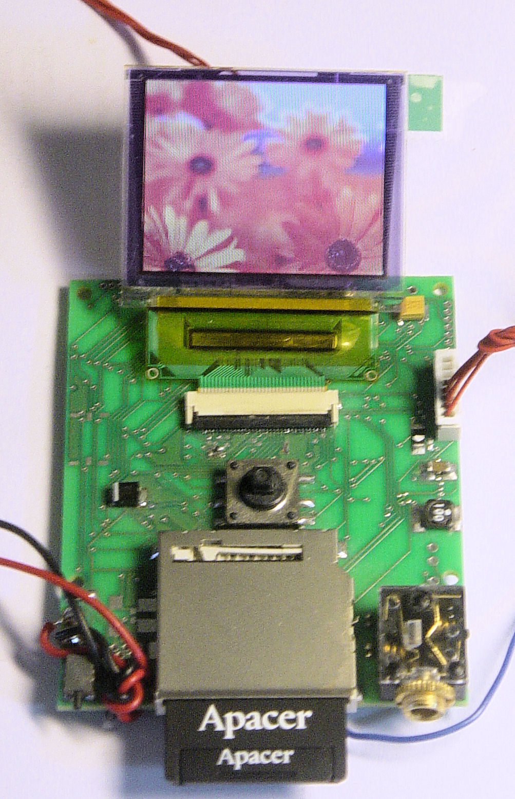
KIT8 + OLED + SD, 4:4:4 No Subsampling YCbCr image decoded
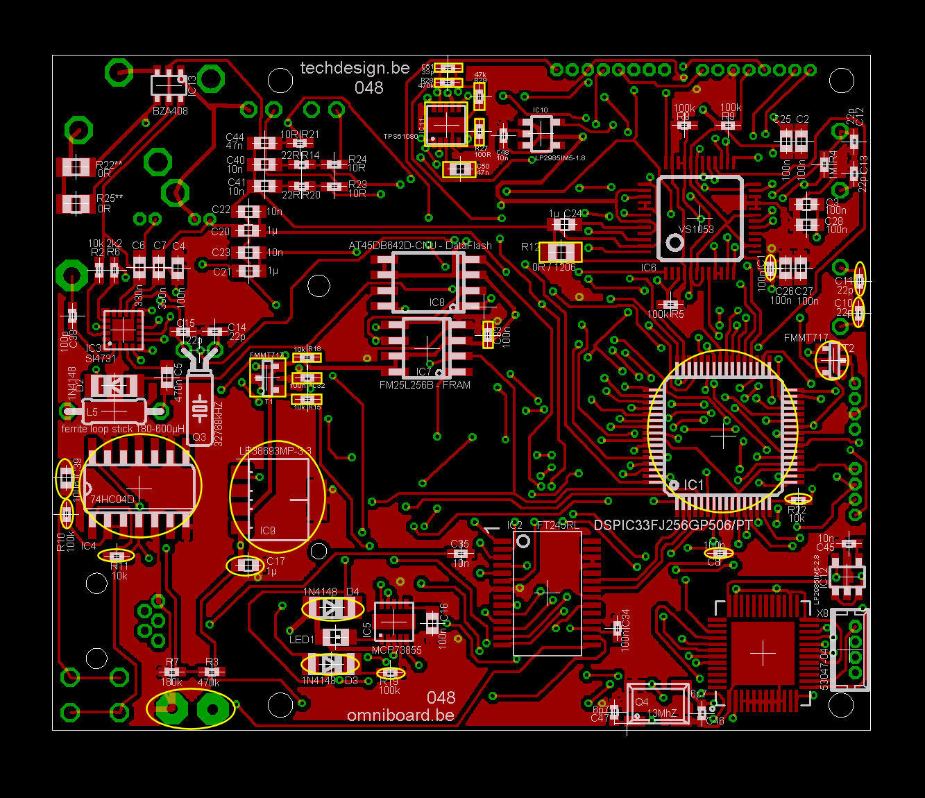
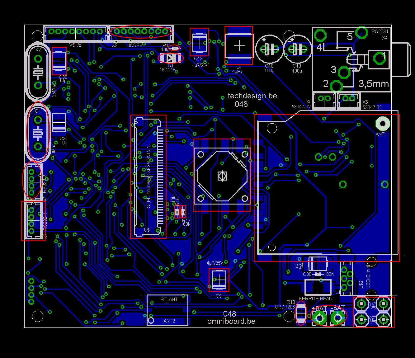
- Schematics: html/gif, pdf, eagle
- PCB diagrams: html
- Partlist: html
- Software: KIT8 example: hex, c code oled
- Bootloader: dsPICprogrammer, dsPICbootloader.hex, howto
- Complete source code (ccs compiler pcwhd) can bought from the webshop.
How to make it work?
- Use a supply or battery between +3V5 ... +6V
- Optional terminal through RS232-1 @ 115200 bpS, 8N1, "type comm"
- MMC or SD(HC) cards must be formatted as FAT16 or FAT32.
RS232 terminal & bootloader.
- Tiny PIC bootloader for 16f and 18F chips.
- For dsPIC chips: our own modified command-line dsPICProgrammer: see omniboard bootloading.
- Or use the Windows 2000/XP terminal screen or third party terminal software.
- RS232 PIC <-> PC hardware interface: how to build it.
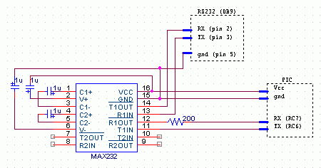
Omniboard ICSP+ (X3 connector) connection pins:
- !MCLR/VPP
- PGD (data)
- GND
- PGC (clock)
- +3v3
- leave open
- leave open
- leave open (closest to pcb corner)
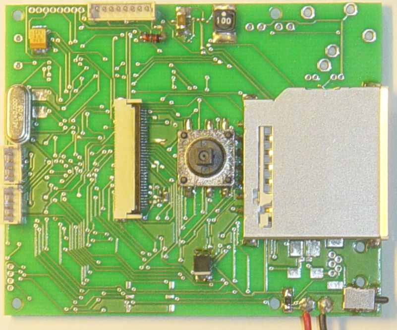
Images: (click images to view full resolution)
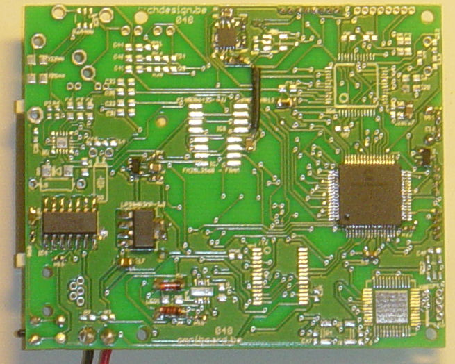
- dsPIC33FJ256GP506-I/L
- VReg LP38693MP-3.3
- Case Serpac M-6
- RGB OLED 160x128 Densitron DD-160128FC-2A
- Dc-up converter TPS61080
- 5-way joystick
Check out our development tools page.
Operation details:
- Jpeg type 1: 4:4:4 No Subsampling YCbCr for best possible quality.
- Type 2: 4:2:2 Vertically subsampled Y1Y2CbCr, the most common format.
- Type 3: 4:2:2 Horizontally subsampled Y1Y2CbCr, (rotated type 2)
- Type 4: 4;2;0 vert. and hor. subsampled Y1Y2Y3Y4CbCr for highest compression.
User Menu: joystick controls:
- Right: open (sub)folder or file
- Left: up one folder level
- Up: select (scroll up) files and folders
- Down: select (scroll down) files and folders
- Enter: back to menu
User Menu: RS232 controls:
- Not supported (yet)
terminal screen output (with all diags on, left click at boot)